A good and useful manual. With these, We was abled to isolate and pin point the component that was causing the problem. The total time spent in troubleshooting is very much reduced.
The product dowload was delivered efficiently with emails to support its download availabilty. The contets of the manual was very eligible and of good quality. Will purchase from this site again!
Text excerpt from page 6 (click to view)
2-1
SERVICE HINTS
REPAIR POSITION COPPERSIDE REPAIR POSITION COMPONENTSIDE
To get access to the copperside of the printed board assembly proceed as follows: 1. Remove the bottom screws (4x) 2. Remove the cabinet screws (4x) 3. Lift the bottom (take care of cabinet/bottom snaps) 4. Supply the unit via external DC-socket
To get access to the componentside of the printed board assembly proceed as follows: 1. Remove the bottom screws (4x) 2. Remove the cabinet screws (4x) 3. Lift the bottom (take care of cabinet/bottom snaps) 4. Lift the printed boards and flip the main board 5. Supply the unit via external DC-socket 6. Short-circuit door-switch 1409 during measurements
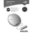
POSITIONING OF SPRING-OPEN
POSITIONING OF SPRING-CD-DOOR
ROUTING OF CD-DRIVE WIRES
Remark: The spring for the CD-door is positioned loose in the cabinet assembly as shown in the picture above. It will be caught in its defined position just after mounting cabinet and bottom parts together.